By George Milad and Don Gudeczauskas
Uyemura International Corporartion
Southington CT
As efforts continue towards meeting RoHS requirements and the elimination of lead, finding the ideal surface finish is on most manufacturers’ minds. The surface finish has to be lead free and able to produce a reliable solder joint when assembled at high temperature with a lead free solder.
There are several surface finishes used by the printed circuit industry. Some finishes are widely used and others are used for very specific applications.
These include:
Gold based Finishes:
- Electroless Nickel / Immersion Gold ENIG
- Electroless Nickel / Electroless Palladium / Immersion Gold ENEPIG
- Direct Immersion Gold (DIG)
Other Finishes:
- Organic Solderability Preservatives OSP
- Immersion Silver IAg
- Immersion Tin ISn
- Selective OSP / ENIG, DIG / ENIG
Most of these finishes have a well documented record of solder joint reliability over time as they have been used for many years with eutectic Sn/Pb solder. The key question now is the solder joint reliability of these finishes if assembled at higher temperatures using lead free alloys.
This article presents lead free (SAC 305 alloy) solder joint reliability data with the gold finishes, namely ENIG, ENEPIG and DIG. SAC 305 is an alloy composed of Sn with 3.0% Ag and 0.5%Cu. SAC alloy has a melting point of 218°C compared to Sn/Pb at 183°C.
Solder balls of SAC alloy and Eutectic Sn/Pb were soldered to BGA pads finished with the different surfaces under investigation. The soldered coupons were then placed in an oven at 150°C from 0 to up to 1000 hours to simulate aging. At different time intervals samples were removed and subjected to ball pull testing. In addition SEM cross sections were also examined.
Sample Preparation for ENIG, ENEPIG and DIG deposition
Sample coupons for evaluation were prepared as follows: copper-clad laminate (FR4) was acid copper plated to 1.0 mil thickness. BGA pads of 0.6 mm diameter were defined with soldermask using commercially available products. A set of coupons were then plated with each of the following surface finishes: Ni-7%P/Au (ENIG) (5μm/0.05μm), (ENEPIG) (5μm/0.06μm/0.03μm) and DIG (0.04μm).
Evaluation Method of Solder Joint and Results
On the various ENIG and ENEPIG sample substrates, solder balls of Sn/37Pb and Sn/3.0Ag/0.5Cu were mounted, followed by heat treatment at 150oC in air for 0, 100, 300, 500, and 1000 hours
to conduct ball pull tests. For the DIG samples only the SAC alloy balls were mounted and ageing was simulated up to 500 hours for ball shear testing and 1000 hours for cross section analysis. The conditions of ball pull tests are shown in Table 1.
Table 1. Ball pull test conditions
| Solder ball | 0.76mm, Sn-37Pb | Solder (Senjyu) |
| 0.76mm, Sn-3.0Ag-0.5Cu | Solder (Senjyu) | |
| Pad Diameter | 0.6mm | |
| Flux | 529D-1 RMA type | (Senjyu) |
| Reflow equipment | TMR-15-22LH | (Tamura) |
| Ball Pull | Dage 4000 | |
| Ball Pull Speed | 170μ |
*Reflow temperature: peak temperature of 240°C
Figure 1 Testing Method schematic
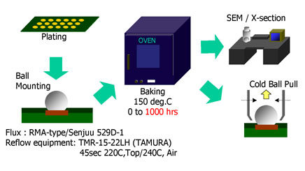
Figure 2. Results of ball pull test when Sn/37Pb was used
Figure 3. Results of ball pull test when Sn/3.0Ag/0.5Cu was used
Figure 1 shows a schematic of the experimental sequence. and the results of ball pull tests are shown in Figure 2 (in the case of Sn/Pb solder) and Figure 3 (in the case of Sn/Ag/Cu solder).
As shown in Figure 2, in the case of Sn/Pb solder, the change of failure mode which indicates a change of the joint interface showed no clear difference when ENIG film was used, but occurred remarkably when ENEPIG was used.
As shown in Figure 3, when Sn/Ag/Cu solder was used, in contrast, minimum change of failure mode was observed in the case of ENIG film, but no change of failure mode was observed in the case of ENEPIG film, exhibiting excellent characteristics.
SEM examination of the different IMCs (intermetallic layers) show that the IMC thickness in general grows over time at elevated temperature. This growth does not impair the solder joint strength of ENIG, ENEPIG or DIG under the conditions of SAC alloy soldering.
As shown in Figure 5, eutectic Sn/Pb SEM examination explained why the ENEPIG failed prematurely with aging. There was irregular areas of excessive IMC growth. This is believed to be the result of the incompatibility of Pd and Pb (no IMC formation). In contrast the IMC formed with ENEPIG and SAC alloy had superior strength and limited thickness. It is theorized that the Pd layer minimized/controlled the diffusion of the Ni into the Sn. Figure 6 shows the intermetallics formed after ageing a solder joint with DIG.
Figure 4. DIG Ball Pull vs Time
For DIG Figure 4, the failure mode did not exhibit significant loss of strength over 500 hundred hours of age simulation.
Figure 5. SEM photographs (1000X)of IMC
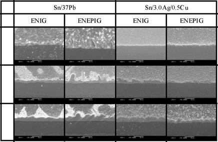
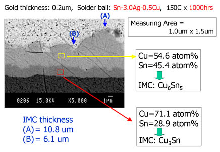
Figure 6. EPMA analysis of DIG with SAC alloy soldering 1000 hrs at 150°C
Conclusion
Both ENIG and ENEPIG form Ni/Sn intermetallic solder joints with the SAC alloy. DIG on the other hand forms a Cu/Sn intermetallic.
ENIG performed very well with both eutectic Sn/Pb and with SAC alloy.
ENEPIG in this investigation proved not to be a suitable finish for eutectic Sn/Pb soldering as was previously believed; it does however produce a superior Ni/Sn solderjoint with SAC alloy
DIG performed real well with both eutectic (not included in this study) as well as with lead free SAC alloy. The absence of Ni in the DIG finish renders it unique for applications where Rf signals are propagated and where Ni may cause an interference. Unlike other immersion processes, DIG solder joints are not prone to voiding.
You may also be interested in this: Study of Suitable Palladium and Gold Thickness in ENEPIG Deposits for Lead-free Soldering and Gold Wire Bonding